Welcome to TheMalibuCrew!
As a guest, you are welcome to poke around and view the majority of the content that we have to offer, but in order to post, search, contact members, and get full use out of the website you will need to Register for an Account. It's free and it's easy, so don't hesitate to join the TheMalibuCrew Family today!
-
Recent Posts
-

Bozboat 5,153
-

JaySmith 0
Thanks for all of the info. Is there a chance it's also a simple calibration issue? The shop I used said that shouldn't affect it but I'd have to imagine since there's a calibration button it's worth a shot.
-
TomN 0
My 2010 Malibu LSV20 is generating “Trans over temp” alerts that appear to be false alarms, as the trans is not heating up and seems to be working fine. We replaced the sensor on the top of the trans and still get the alert. We then disconnected the sensor altogether, and we STILL get the alert.
Anyone have any ideas, and/or a wiring diagram for this boat so we can try to track down or isolate? At this time, we believe the problem might be in the wiring between the connector to the sensor and the dashboard display, as the wires coming out of the connector to the sensor seem to be routed to the throttle control box and not to the ECU.
Any ideas help (. Or wiring diagrams) are appreciated. -

csleaver 1,336
There are two screw terminals on the power module under the helm labeled power wedge (black) with a black wire, and power wedge (white) with a white wire (see previous photo). You can switch those wires to make the power wedge move opposite of the way you are controlling it with the MUX. Using a voltmeter to test the voltage and ground on those terminals when running the wedge up or down can also help determine what the problem may be.
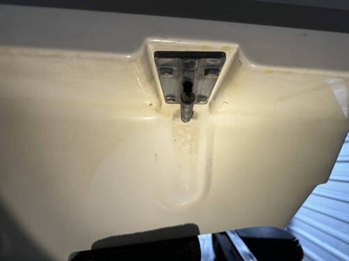
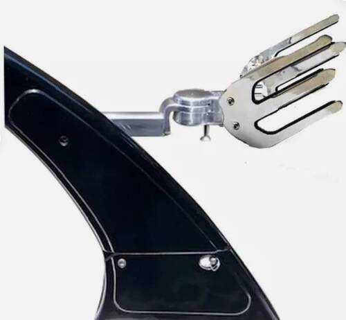
Please don't overlook the other suggestions. The most common issues I've seen after actuator replacement is loose electrical connections, the wedge wing binding, or the power wedge adjustment bracket not being properly adjusted for the actuators.
Edited by csleaver -

justgary 7,011
... and that means that if it is really a straight pipe thread, it should be 1.5" pipe. That would also make it actually 11.5 TPI. Hard to measure the cap with the huge flange and all.
Edit: I just compared it to a pipe thread, and it looks like 11 TPI rather than the 11.5 that pipe thread is supposed to be. Total diameter is 3.5" and it is 1" thick, by the way.
Edited by justgary
-
-
Who's Online 31 Members, 0 Anonymous, 339 Guests (See full list)
- BvrGuy
- butter71
- fullthrottle
- Ronnie
- BlindSquirrel
- 23LSVOwner
- BillFooter
- bretcole
- jjackkrash
- Tractorkid1
- Horns1
- mrothwell
- redrooster
- Cole2001
- BPAUL1033
- Nick55
- Rack
- csleaver
- Golddigger2
- DFW
- Tville
- SpartanVTX
- dshack
- Roosk
- REHinH20
- JaySmith
- RyanB
- Stevo
- llorgon
- BLSousa
- solorex
-
Member Statistics
42,463
Total Members8,865
Most Online
-
Classifieds
-
$1
-
-

$200
-

$200
-
-
Recent Status Updates
-
MattM10 » csleaver
How do I rule out the Viper II Black Box as my issue? I'm getting CAN 2 Error. I've checked almost every positive and ground connection for looseness and corrosion. We have brand new batteries. We had it working great last night for about 10 minutes and then the volume, blower, lights all stopped working again.· 5 replies
-

Coachman51
Just purchased my first boat last week. Can't wait to put her in the lake and see what she can do. A beautiful 1996 Malibu Response 20 (closed bow) that has been meticulously carred for by her first 2 owners. I am thrilled to be her 3rd owner. Found a diamond to behold. Should be a great boating season on the horizon. 🤞· 0 replies
-

dalt1 » EchelonMike
I'll save a 2022 brochure for you. Waiting a week or two so I can make one trip to USPS instead of 12. Costs can be as high as nearly $20 to some addresses but you are close so will let you know.· 2 replies
-
-

Sasquatch
I found rusty particles in my fuel injectors. I'm suspecting they came from bad gas from a gas station with old underground tanks. I'll be checking out my tank for the offending mass of rusty particles. I hope its not a failing fuel pump. Anyone find rusty particles after had to change out a fuel pump?· 0 replies
-
-
Recent Topics
-
-
Latest Images
-