Jump to content

Welcome to TheMalibuCrew!

As a guest, you are welcome to poke around and view the majority of the content that we have to offer, but in order to post, search, contact members, and get full use out of the website you will need to Register for an Account. It's free and it's easy, so don't hesitate to join the TheMalibuCrew Family today!

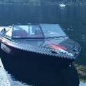
Building and Swapping an LSx into an Old Skier


Recommended Posts

A few of us have taken down the 60mph barrier...

This is pretty impressive with an inboard. Not such a big deal with an outboard or I/O where you can "trim it up".

  • Like 2
Link to comment
  • 2 weeks later...

Been waiting on some parts and having a hard time finding time to work on the boat, parts are in though. I already talked about the adapter brackets from LS to SBC mount pattern, I ordered SBC engine mounts from SKIDIM, they bolted right up. Only thing I changed was I drilled out the tapped holes in the adapters and put 3/8" bolts in instead, there is just enough space for the head of the bolt. I ran into a problem with the bottom hole as it is blocked by the design of the mount so I have to find some 10 x 1.5 threaded rod to put into the block before the mount itself goes on.

I was trying to come up with a way to attach a drain line to the oil pan to make oil changes easier. I couldn't find an adapter to go from the GM oil pan plug thread to 8an, its and oddball thread, so I took the pan off and drilled and tapped the drain hole with 3/8"npt and threaded in a 3/8"npt to 8an 90* adapter. I added about a couple of feet of hose with a female end installed, I'll be plugging that, then can easily add an extension for draining.

post-21878-0-09252000-1432475122_thumb.j

post-21878-0-81026600-1432475504_thumb.j

post-21878-0-31916000-1432475532_thumb.j

Edited by 2014Skier
Link to comment

All the threads on these LS motors are metric, so its a bit of a hassle to fit your typical 1/8"npt guage senders to the head and block for oil pressure and engine temp. I got two adapters off of eBay for cheap in a LS conversion set that convert the metric threads in both the head and block to 1/8"npt. The oil pressure pickup is on the back top portion of the block and the coolant temp sensor is on the cylinder head, the one for the ECU is front right, so I added my gauge sender to the rear left.

post-21878-0-56622000-1432475851_thumb.j

post-21878-0-20989800-1432476103_thumb.j

Link to comment

So one of the issues is adapting the LS motor to the Velvet Drive. I haven't been able to find any info abou this so I'm flying blind on this part. I know that the old SBC bell housing will bolt up to the LS block so no problem there. The rear crank spacing on LS motors is 0.4" different then the SBC, however you can get conversion kits to mate LS motors to old GM trannies. The best, or what I think is the best solution was to get a Sachs 1050 flywheel, these flywheels bolt to LS motors however the way they are designed they take up the extra 0.4" spacing difference to in effect move the mating surface to the same position as found in the old SBC. The flywheel looks normal from the front, just really thick, but the back has a recess cast into it so its not that heavy. Once I had the flywheel I measured the mounting bolt pattern where the damper plate would be mounted too. From my Velvet Drive rebuild experience I know that both the 71 and 72 series Velvet Drives use the same size splined input shafts. So I went ahead and ordered a BBC damper plate with 8 springs in it as opposed to the 5 that the SBC plates have, it bolts right up real nice. In my mind this will all work perfectly, when I mate the trans to the bell housing...I guess we'll see.

post-21878-0-05899700-1432476283_thumb.j

post-21878-0-25516400-1432476289_thumb.j

post-21878-0-61726600-1432476300_thumb.j

Link to comment

One of the things that I wanted to improve on was the factory PCV system, LS intake manifolds tend to ingest oil through the PCV system which leads to its own problems. So I'm adding two catch cans, one for the clean side and one for the dirty. I'll be plumbing the system with 10an lines to keep the air velocity low and using a fixed orifice style PCV "valve". I welded 10an bungs onto both the drivers and passenger side valve covers, the lines will run from the drivers side to the dirty catch can and then from that catch can to the back of the intake manifold where I am tapping a 3/8"npt port. I will add a 10an adapter to this port. I will tap the inside of this 3/8"npt adapter and thread in a plug with a hole in it, and bingo...fixed orifice PCV.

The clean side with go from the air filter to the catch can and then from the catch can to the passenger side valve cover. Under normal conditions clean air will be sucked through this part of the system into the crankcase. However under heavy load, the blow by may, or will most likely, exceed the flow capacity of the dirty side, in this case there will be blow by flowing out what would normally be the intake or clean side, hence the two catch cans. There will potentially be also be a slight vacuum on the intake side as the air filter will cause a slight restriction under high air flow which will help suck out the extra blow by.

The cans will be mounted side by side on the front of the cylinder head.

post-21878-0-80956500-1432477054_thumb.j

post-21878-0-73031500-1432477062_thumb.j

post-21878-0-84426300-1432477070_thumb.j

  • Like 1
Link to comment
  • 3 weeks later...

I've got the transmission mounted up now, and I rebuilt all the mounts, the engine and trans are now sitting on a cradle on a dolly. Everything worked out just like I hoped with the flywheel and damper plate, the spline engagement on the input shaft to the VD is bang on. I gave everything a coat of paint before and after bolting it on to try to slow down any rusting of parts. The Bellhousing bolted right on, there is one bolt hole that doesn't line up but there are still 5 bolts holding it on. I checked to make sure the bellhousing was centred with in spec using a magnet base dial indicator mounted on the crank, it came out to a total of 0.010" total , but half that, and it's 0.005" which is fine.

post-21878-0-11396000-1433946013_thumb.j

post-21878-0-94918900-1433946020_thumb.j

post-21878-0-75758000-1433946091_thumb.j

Link to comment

Next I started tackling the raw water pump, I was hoping to be able to re-use the one that I had from the Ford, it's a Sherwood G-21 a pretty common pump from what I can tell. I took it apart and ordered a complete rebuild kit with new bearings etc etc, after I realized it would fit. I took the mount off the Ford and just started looking for a place to mount it, as it turns out there is a mounting pad for where what I think was the A/C compressor on the side of the engine, and using the top hole of the pump bracket allows the pump to line up nicely with the 4 groove A/C pulley. I could hardly believe it. All I had to do was get a piece of 1/4 plate and drill three holes in it, two for the 10x1.5 bolts that go into the block and another for a 3/8" bolt that just pinches the mount to the plate. I painted it all up and bolted it on, seems pretty sturdy. I'll be able to use the 4 groove pulley on the damper and ordered a power steering pulley I'll put on the pump shaft.

post-21878-0-70466100-1433946537_thumb.j

post-21878-0-35260900-1433946544_thumb.j

post-21878-0-05183300-1433946555_thumb.j

Link to comment

The last thing I need to do to the intake before bolting it back on was to tap a 3/8" npt hole in the back of it where an existing vacuum hose barb was, I then got a 3/8" npt to 10an adaptor and drilled out the centre of it from the backside about halfway through the fitting. I then tapped this hole with a 1/4" npt tap and plugged the hole with a 1/4" npt brass plug. In this plug I drilled a 0.1065" hole, this hole is what will control the flow of the crank case ventilation, basically a controlled vacuum leak.

post-21878-0-43296300-1434199445_thumb.j

post-21878-0-19702900-1434199452_thumb.j

Link to comment

Last night I had some time to get some more work done. I got the intake manifold bolted on for the final time and the steam vent plumbing run. The LS motors have the provision for steam vents in the cylinder heads, one at the front and one at the rear. From my understanding in the early years GM used all four from the factory, this changed to the two front ones in later years. There is much controversy over these steam vents over on the LS forums, the reason they are there is to.....surprise, vent the steam that could accumulate in the high portion of the coolant paths in the heads. After doing all my research I decided to use all four and route them into the low pressure side of the water pump, the road race guys seem to like to do it this way. When I was dealing with the heads prior to install I drilled and tapped each existing hole in the cylinder heads 1/8"npt and adapted it to 4an. To build the system I got a nitrous distribution block 4 to 1 and mocked that up on the top of the intake. Then ran lines from all four corners to the block. I had previously tapped and installed an adapter in the water pump too. So, when running the lower pressure on the suction side of the water pump will draw coolant from the cylinder head passages into the water pump, this will help eliminate any hot spots in the cylinder heads, and if any steam pockets develop this should pull them out. There are a few places that sell kits for this but I didn't really like any of them for the price. I know the plumbing is floating around right now but I will clean it up once I get the cover plate for the intake made.

post-21878-0-09521700-1434291749_thumb.j

post-21878-0-55491700-1434291757_thumb.j

Link to comment

Wow, compared to my little carbed SBC I don't even know what that is!

You might have already covered this, are you doing something custom to the engine cover to make it taller? Is that set up going to fit?

Link to comment

Hey MB. There's a lot to be said about the SBC, with a carb on it. Simple, reliable, and you got some good power out of yours.

I can't remember the numbers but I did measure the height pan to flame arrestor on the old Ford and pan to intake on the LS. I think they were quite similar. The mounts are not adjusted properly right now. So the should drop some height. I think the real test will be the exhaust, it's sitting in my p.o. box so should know soon. Though with the tilt in the motor and the flame arrestor being in the middle vs the intake running the whole length it may be an issue. The LS3 intakes are shorter but not ideal for what I'm running.

I actually LOVE the power plant I have, I'm really glad with the whole direction we took. Reading thru so many threads with guys chasing problems, my diagnostics are pretty quick & easy, not a whole lot to it. I've pretty much maxed my level of competence and (I think) can maintain it well. I was just amazed at how different yours looks. Looking forward to your water test!

Link to comment

It's great to hear you're loving you new motor. I'm curious about the prop your running, same one as before just turning it faster so the hole shot is still good,what's the max rpm she pulls?

So I got my new marine alternator in, it's a 7si serries. I decided to take it apart to see how they do the ignition suppression. The only place that sparks are created is between the brushes and the rotor. In the 7si the brushes and rings are contained in a housing, the housing has a orange rubber seal on it, that's it, nothing else. So I took the cover off the back of my cs130-d and the plastic housing around the brushes and rings is pretty much identical. So, I'm gonna take that little orange ignition suppressor and install it on my cs130-d and bingo...I'll save the 7si for another project.

Pics to follow.

post-21878-0-33079600-1434762311_thumb.j

Edited by 2014Skier
Link to comment

I just checked it out 2 days ago. 44.5mph (gps) and 5,250 rpm, and that is the stock prop. So I need to reprop, to get the max out of it. We surfed and cruised around yesterday, the current one will get me thru the season but to take full advantage of the new power I definitely need something different, you can feel it slip.

Link to comment
  • 2 weeks later...

So work on the LSx is nearing completion. I rebuilt the Sherwood G21 raw water pump that was on the old Ford 351 Marine Power. Best place I found for the kit was e-Bay, I got the complete kit with new bearings, seals, etc etc. Pretty easy little project, got it all back together and painted it up. I can't remember if I touched on it, but I cut/pressed the old v-belt pulley off the pump and looked for a serpentine belt alternative. The LS crank pulley has a 4 groove pulley that was originally used for the AC compressor. Looked like it would line up just nice, so I ordered a Dorman power steering pump with the same bore diameter and approximate pulley OD and put it on, its and 8 rib, so there is no alignment issues, just gotta choose which groves I wanna use.

The other thing that I got taken care of was the fuel filter / water separator. I ordered a generic filter base from Napa which will use the Napa / Wix filters, its got 1/2" npt in and out on it, so got the 1/2" npt to 8an adapters out and found a good mounting spot for it on the back of the cylinder head. Pretty simple install an should to the trick.

I'm running out of stuff to do to the motor / trans combo prior to install, just gotta put the throttle body back on, plumb the PCV system, install the belts, and exhaust manifolds, at least I think that is all.

post-21878-0-01372800-1435916045_thumb.j

post-21878-0-69718100-1435916049_thumb.j

post-21878-0-12461000-1435916056_thumb.j

Edited by 2014Skier
Link to comment
  • 2 weeks later...

So this is pretty much the end of this thread, well at least from what I can tell.... I think. The motor/trans are basically ready to drop in minus knock sensor install, riser install, and air filter install, which I need to finish the PCV system.

The manifolds are from a PCM, ZR 409, SKIDIM had them at the best price, not the best flowing, but real nice headers/manifolds are out of my price range for now. I know I will be taking a hit in the power department with these, but its all I can afford for now so it'll have to do, maybe upgrade in a few years to some nice Hi-tek one's.

I'll have to modify one of the risers for an O2 sensor, but not a big deal.

As I mentioned this thread may not be dead yet, but the install of the engine/trans I'm going to cover in the "Saving a Square Windshield 'Bu thread"

Hope you all enjoyed the engine p***.

Steve.

post-21878-0-05999100-1437189563_thumb.j

post-21878-0-43915400-1437189706_thumb.j

  • Like 3
Link to comment

Join the conversation

You can post now and register later. If you have an account, sign in now to post with your account.

Guest
Reply to this topic...

×   Pasted as rich text.   Restore formatting

  Only 75 emoji are allowed.

×   Your link has been automatically embedded.   Display as a link instead

×   Your previous content has been restored.   Clear editor

×   You cannot paste images directly. Upload or insert images from URL.

×
×
  • Create New...